Scrubber systems are a wide variety of air pollution control devices that can be used to remove some particles and / or gases from industrial exhaust streams. The first air cleaner was designed to remove carbon dioxide from the air of an old submarine, and this task continues to be used today. Traditionally, the term “Scrubber” refers to pollution control devices that use liquid to wash unwanted contaminants from a gas stream. Recently, the term has also been used to describe systems that inject a dry reagent or slurry into a dirty exhaust stream to “wash” acid gases. Sucrubbers are one of the primary devices that control gas emissions, especially acid gases. Scrubbers can also be used for flue-gas condensation and heat recovery from hot gases. They are also used for high flows in solar, PV or LED processes.
Flue Gas Desulfurization (FGD)
Flue Gas Desulfurization (FGD) is a series of technologies used to remove sulfur dioxide (SO2) from emissions of sulfur oxide emitting processes such as exhaust flue gases and waste incineration of fossil fuel power plants and vehicles.
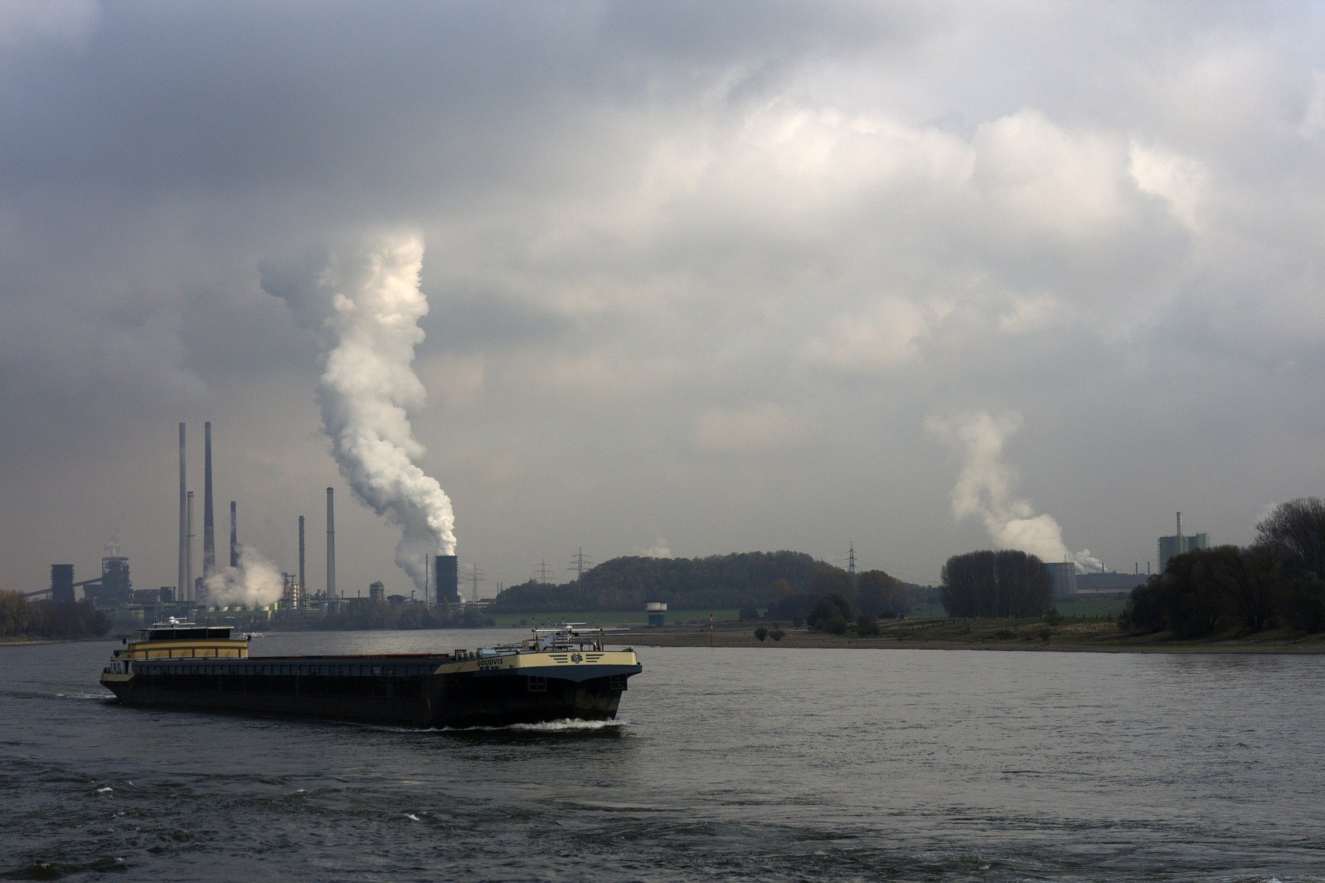
Scrubber on ships
Scrubberss were first used for the production of Inert Gas for oil tanker operations on ships.
The International Maritime Organization (IMO) then adopted guidelines for the approval, installation and use of exhaust gas scrubbers (exhaust gas cleaning systems) on ships to ensure compliance with the sulfur regulation in preparation for the global 0.5% sulfur limit in 2020 MARPOL Annex VI.
Flag States must certify such systems, and port states inspect the correct functioning of these systems as part of port state controls. The United Nations Convention on the Law of the Sea gives port States the right to regulate and even prohibit the use of open loop scrubber systems in ports and inland waters. If the scrubber system is not working properly and IMO procedures are not followed, the port States may impose sanctions on the ship.
Flue gas desulfurization methods
Since strict environmental regulations limiting SO2 emissions have come into force in many countries, SO2 is removed from flue gases by various methods.
Common methods used:
- Wet scrubbing, usually using an alkaline sorbent slurry (sorbent – a material used to absorb liquids or gases) or seawater to clean gases;
- Dry brushing by spraying similar sorbent slurries;
- Wet sulfuric acid process, which regains sulfur in the form of commercial grade sulfuric acid;
- SNOX Flue gas desulfurization separates sulfur dioxide, nitrogen oxides and particles from flue gases;
Dry absorbent injection systems that introduce powdered hydrated lime (or other sorbent material) into the exhaust ducts to eliminate SO2 and SO3 from process emissions.
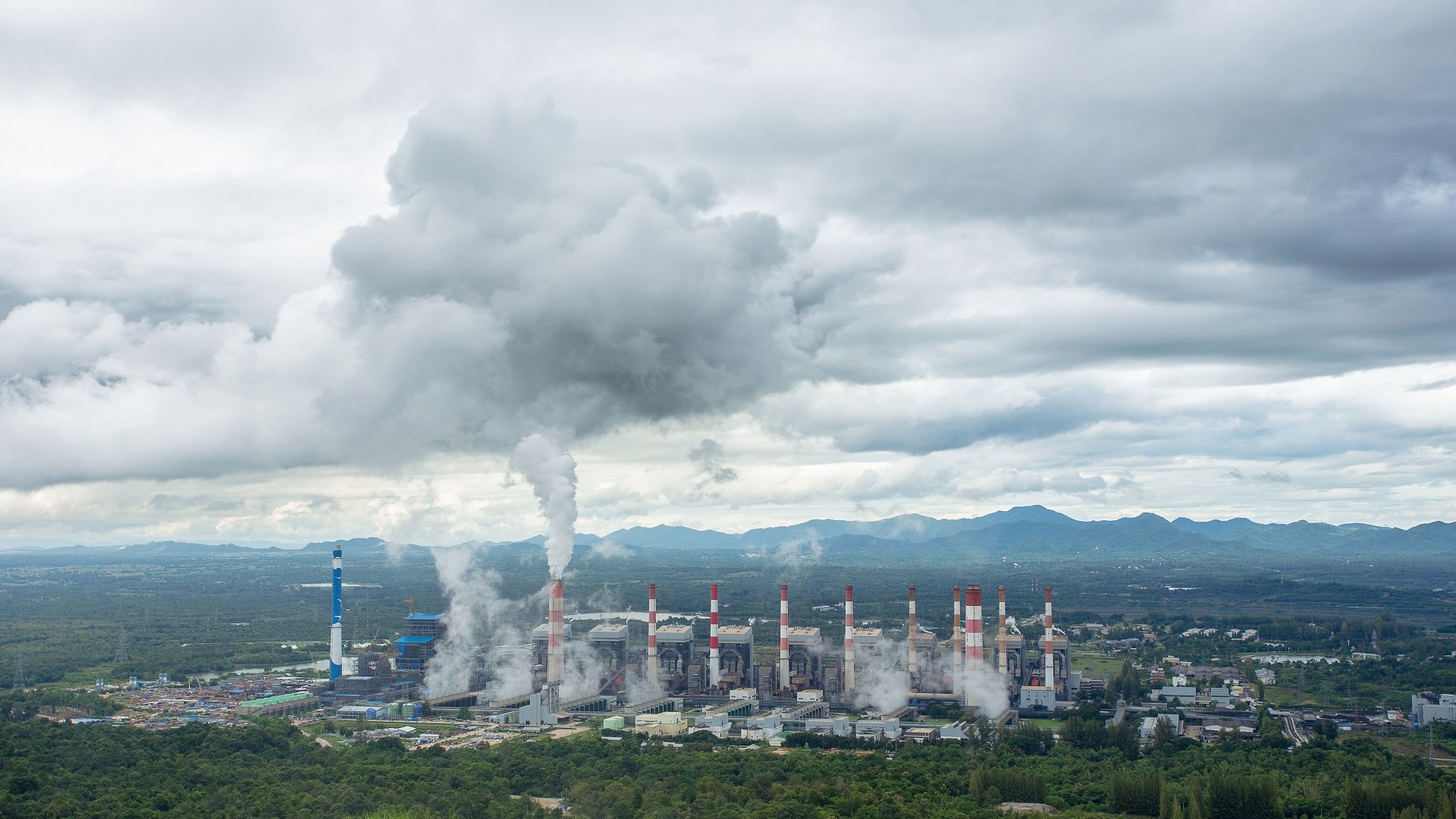
For a typical coal-fired power plant, flue gas desulfurization (FGD) can remove 90 percent or more of SO2 in flue gases.
Sulfuric acid vapor formation
Fossil fuels such as coal and oil can contain significant amounts of sulfur. When fossil fuels are burned, about 95 percent or more of sulfur is generally converted into sulfur dioxide (SO2). This type of conversion takes place under normal temperature and oxygen conditions found in the flue gas.
There are several methods for removing and neutralizing toxic or corrosive compounds from exhaust gas;
Combustion
Combustion is sometimes the cause of harmful exhausts, but in most cases, combustion can also be used for exhaust gas cleaning if the temperature is high enough and enough oxygen is available.
 Wet Scrubber
 Wet Scrubber
The term wet scrubber describes various devices that separate pollutants from a furnace flue gas or other gas streams. In a wet scrubber, the dirty gas stream is brought into contact with the scrubbing liquid by spraying the liquid, passing it through a pool of liquid, or another contact method to remove contaminants.
Wet scrubbers are used in various industries such as acid factories, fertilizer plants, steel plants, asphalt plants and large power plants.
The exhaust gases of combustion contain substances that are considered harmful to the environment, the washer removes or deactivates them. A wet scrubber can be used to clean air, fuel gas or other gases of various pollutants and dust particles.
Wet scrubbing works by contacting the target compounds or particulate matter with the wash solution. These can be simply water or solutions of reagents specifically targeting specific compounds.
The process may contain water-soluble toxic and / or corrosive gases such as exhaust gas, hydrochloric acid (HCl) or ammonia (NH3).
Contaminant removal efficiency is improved by increasing the residence time in the washer or by increasing the surface area of the scrubber solution using a spray nozzle, packed towers or an aspirator.
Wet scrubbers can also be used for flue-gas condensation and heat recovery from hot gases. In this mode, called a condensing washer, the water from the washer drain is circulated through a cooler to the nozzles on the washer. Hot gas enters the scrubber from below. If the gas temperature is above the water dew point, it is initially cooled by the evaporation of the water droplets. More cooling causes the water vapors to condense and increase the amount of circulating water.
Dry Scrubbers
The dry or semi-dry scrubbing system, unlike wet scrubbers, does not wet the flue gas stream. In some cases, moisture is not added, while in others only the amount of moisture that can be evaporated in the flue gas. For this reason, dry scrubbers generally do not have wastewater treatment and disposal requirements. Dry cleaning systems are used primarily to remove acid gases from combustion sources.
Dry scrubbing systems can be categorized as dry absorbent injectors (DSIs) or spray drying absorbers (SDAs). Spray dryer absorbers are also called semi-dry washers or spray dryers.
Scrubber waste products
A side effect of the scrubbing process is that the process turns the unwanted substance from the exhaust gases into a liquid solution, solid paste or powder. If they cannot be reused, they must be disposed of safely.
As an example of reuse, limestone-based scrubbers in coal-fired power plants can produce synthetic gypsum of sufficient quality that can be used in the production of drywall and other industrial products.
Design
The design of wet scrubbers or any air pollution control device depends on the industrial process conditions and the nature of the air pollutants involved. Inlet gas properties and dust properties (if particles are present) are of primary importance. Scrubbers are designed to collect particulate matter and / or gaseous contaminants. The versatility of wet scrubbers allows them to be installed in a variety of configurations, all designed to provide good contact between liquid and dirty gas flow.
Wet scrubbers remove gas and dust particles by trapping them with liquid droplets. The droplets are then collected, dissolving or absorbing liquid, pollutant gases. In addition, the resultant scrubbing liquid must be treated at the facility before any final discharge or reuse.
The ability of a wet scrubber to collect small particles is often directly proportional to the power input to the cleaner. Low-energy devices such as spray towers are used to collect particles larger than 5 micrometers. High-energy devices such as venturi scrubbers or augmented devices such as concentrator washers are often required to ensure highly efficient removal of 1 micrometer (or less) particles.
In addition, a properly designed and operated drag splitter or demister is important to achieve high cleaning efficiency. The more liquid droplets that are not caught by the fogger, the higher the potential emission levels.
Wet scrubbers that remove gaseous contaminants are called absorbers. Good gas-liquid contact is required to achieve high removal efficiency in absorbers. Various designs of wet scrubbers are used to remove gaseous contaminants; packed tower and the most common is the plate tower.
If the gas stream contains both particulate matter and gas, wet scrubbers are usually an air pollution control device that can remove both contaminants. Wet scrubbers can provide high cleaning efficiency for particles or gases and, in some cases, a high removal efficiency for both contaminants in the same system.
However, in most cases the best operating conditions for particle collection are the poorest for degassing.
In general, achieving high simultaneous gas and particle removal efficiencies requires either one to be easily collected (i.e. the gases are very soluble in liquid or the particles are large and easily captured) or made using a scrubbing reagent (such as lime or sodium hydroxide).
Advantages and disadvantages
- Wet scrubbers have the ability to handle high temperatures and humidity,
- In wet scrubbers, flue gases are cooled, which requires smaller equipment size,
- Wet scrubbers can clean both gases and particulate matter,
- Wet scrubbers can neutralize corrosive gases,
Some disadvantages of wet scrubbers are; corrosion is the need for drag separation or demisting to achieve high efficiency, and the need to treat or reuse used fluid.
Wet scrubber types used in FGD
A range of wet scrubber designs have been used to support maximum gas-liquid surface area and residence time, including spray towers, venturis, plate towers, and mobile packed beds. Simple scrubbers, such as spray towers, are used instead of more sophisticated ones to increase FGD reliability and absorbent efficiency and eliminate clogging or erosion. The configuration of the tower can be vertical or horizontal and the flue gas moves simultaneously, reverse or cross flow with respect to the liquid. The main disadvantage of spray towers is the requirement for a higher liquid-gas ratio for equivalent SO2 removal compared to other absorber designs.
FGD scrubbers produce wastewater that requires treatment to meet US federal discharge regulations. However, technological advances in ion exchange membranes and electrodialysis systems have enabled high-efficiency treatment of FGD wastewater to meet the latest EPA discharge limits. The treatment approach is similar to other highly scaled industrial wastewater.
 Venturi rod scrubbers
 Venturi rod scrubbers
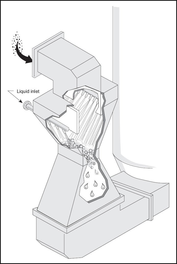
The design of a venturi scrubber is similar to an hourglass, increasing the flow of gas to high velocity. When the liquid stream is injected through the throat, the maximum velocity point, the turbulence caused by the high gas velocity atomizes the liquid into small droplets, which creates the surface area required for mass transfer to occur. The higher the exhaust pressure drop in the venturi, the smaller the droplets and the higher the surface area. The biggest disadvantage of the Venturi washer is its high power consumption.
Venturi scrubbers can be used to simultaneously remove SO2 and fly ash. In fact, most industrial sodium-based disposable systems are venturi scrubbers originally designed to remove particulate matter. These units were slightly modified to inject a sodium-based scrubbing liquid. Although it can be economical to remove both particles and SO2 in a container, the problems of finding a wash medium to remove the heavy loads of high pressure drops and fly ash should be taken into account. However, in cases where the particle concentration is low, such as oil-powered units, it may be more effective to remove the particle and SO2 at the same time.
Package bed scrubbers
A packed scrubber consists of a tower with packing material inside. This packaging material can be in the form of saddles, rings or some highly specialized shapes designed to maximize the contact area between dirty gas and liquid. Packed towers typically operate at much lower pressure drops than venturi scrubbers and are therefore more economical to operate. They also typically offer higher SO2 removal efficiency.
The disadvantage is that they have a greater tendency to blockage if there are excess particles in the exhaust air stream.
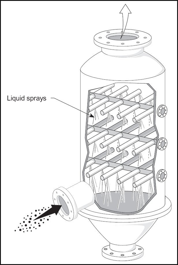
Spray towers
The spray tower is the simplest type of washer. It consists of a tower with a spray nozzle that creates droplets for surface contact. Spray towers typically wash with a slurry.
While the high velocity of a venturi causes erosion problems, there is a risk of clogging in spray towers that circulate dense slurry. Countercurrent filled towers are rarely used as they tend to become clogged by collected particles or scaling when lime or limestone wash slurries are used.
Scrubbing reagent
As explained above, alkaline sorbents are used to clean flue gases to remove SO2. Depending on the application, the two most important are lime and sodium hydroxide (also known as caustic soda). Lime is typically used in large coal or oil-fired boilers, such as in power plants, as it is much cheaper than caustic soda. The problem is that it results in circulating a slurry in the washer rather than a solution.
This complicates the work of the equipment and a spray tower is typically used for the application. The use of lime results in a calcium sulfite slurry (CaSO3) that must be disposed of. Fortunately, calcium sulfide can be oxidized to produce by-product gypsum (CaSO4 2H2O), which can be marketed for use in the building products industry.
Caustic soda is limited to smaller combustion units as it is more expensive than lime, but has the advantage of forming a solution rather than a slurry. This makes it easy to operate. It produces a “spent caustic” sodium sulfite / bisulfite (pH dependent) or sodium sulfate solution that must be disposed of.
Scrubbing with sodium sulfite solution
It is possible to remove sulfur dioxide using cold sodium sulfite solution; this creates a sodium hydrogen sulfide solution. By heating this solution, it is possible to reverse the reaction to form sulfur dioxide and sodium sulfite solution. Since the sodium sulfite solution is not consumed, it is called regenerative treatment. The application of this reaction is also known as the Wellman-Lord process.
Gas phase oxidation followed by reaction with ammonia
A newly emerging flue gas desulfurization technology has been defined by the IAEA. It is a radiation technology in which a dense electron beam is fired into the flue gas while ammonia is added to the gas. The Chendu power plant in China launched such a flue gas desulfurization unit on a 100 MW scale in 1998. The power plant Pomorzany in Poland also installed a similar-sized unit in 2003, which cleans both sulfur and nitrogen oxides. Both facilities are reported to be operating successfully.
The process does not require or generate radioactivity. The electron beam is produced by a device similar to the electron gun in a TV set. This device is called an accelerator. This is an example of a radiation chemistry process where the physical effects of radiation are used to process a substance.
The effect of the electron beam is to promote the oxidation of sulfur dioxide to sulfur compounds. Ammonia reacts with the sulfur compounds thus formed to produce ammonium sulphate, which can be used as nitrogen fertilizer. It can also be used to reduce the nitrogen oxide content of the flue gas. This method has reached the scale of industrial facilities.
Alternative methods to reduce sulfur dioxide emissions
An alternative to desulfurization of flue gases formed after combustion is to desulfurize the fuel before or during combustion.
Hydrodesulfurization of fuel has been used for processing fuels before use. Fluidized bed combustion adds lime to the fuel during combustion. Lime reacts with SO2 to form sulfates that become part of the ash.
This elemental sulfur is then decomposed and finally recovered at the end of the process for use, for example, in agricultural products. Since the whole process takes place at atmospheric pressure and ambient temperature, its reliability is one of the biggest benefits of this method. This method was developed by Paqell, a joint venture of Shell Global Solutions and Paques.
History
Methods of desulfurization of sulfur dioxide removal from boiler and furnace exhaust gases have been studied for over 150 years. The first ideas for flue gas desulfurization were established around 1850 in England.
With the construction of large-scale power plants in Britain in the 1920s, problems with large volumes of SO2 from a single region began to worry the public. The issue of SO2 emissions did not attract much attention until 1929, when the House of Lords confirmed a landowner’s claim against the Manchester Corporation’s Barton Electric Works for damages from SO2 emissions.
Shortly after, a media campaign was launched against the establishment of power plants within the boundaries of London. This outcry led to the imposition of SO2 controls on all such power plants.
The first large FGD unit in a public institution was established in 1931 at Battersea Power Station owned by London Power Company. In 1935, a FGD system similar to that installed at Battersea was put into service at the Swansea Power Plant. The third largest FGD system was installed at Fulham Power Plant in 1938. These three large-scale FGD facilities were suspended during World War II because the characteristic white vapor clouds would take a decisive position by enemy aircraft. The FGD factory in Battersea was re-commissioned after the war and was operated together with the FGD plant at the new Bankside B power plant across the City of London until it closed in 1983 and 1981, respectively.
Large-scale FGD units did not reappear in utility services until the 1970s, when most installations took place in the United States and Japan. In 1970, the US Congress passed the Clean Air Act of 1970 (CAA). The law led to the development of federal regulations in the United States, which were later published by the US Environmental Protection Agency (EPA), covering emissions from both industrial, stationary and mobile sources. In 1977, Congress changed the law to require stricter controls on air emissions. In response to the CAA requirements, the American Society of Mechanical Engineers (ASME) authorized the creation of the PTC 40 Standards Committee in 1978. This committee first convened in 1979 to develop a standard procedure for conducting and reporting performance tests.
The first bill was approved by ASME in 1990 and was passed by the American National Standards Institute (ANSI) in 1991. The PTC 40-1991 Standard was available to the public for units affected by the 1990 Clean Air Act Amendments. In 2006, the PTC 40 Committee was reunited following the EPA publication of the Clean Air Interstate Rule (CAIR) in 2005. The revised PTC 40 Standard was published in 2017. This revised standard (PTC 40-2017) covers Dry and Renewable FGD systems and provides a more detailed Uncertainty Analysis section. This standard is currently used by companies around the world.
As of June 1973, 42 FGD units were operating, with capacities ranging from 5 MW to 250 MW, 36 in Japan and 6 in the United States. As of approximately 1999 and 2000, FGD units were in use in 27 countries and there were 678 FGD units operating at a total power plant capacity of approximately 229 gigawatts. Approximately 45% of FGD capacity was in the USA, 24% in Germany, 11% in Japan and 20% in various other countries. Approximately 79% of the units, representing approximately 199 gigawatts of capacity, were using wet scrubbing with lime or limestone. About 18% (or 25 gigawatts) used spray dryers or absorbent injection systems.